This page is dedicated to those do it yourself modifications and fixes which members of IWOC have undertaken on their car in the name of safety, experimentation, performance, irritation and boredom. As always with these sort of things....beware that these mods may affect your warranty and we take no responsibility if you do one of these mods and it does not work (or worse).
Xenon bulbs
The first thing any UK owner (other markets should check) should do is upgrade the bulbs in their headlights to the 50% extra Xenon Plus H4 replacements. The Impreza was not graced with very good lighting comparative to its performance and these bulbs go some way to redressing the problem. It is not recommended to go for higher wattage as the plastic reflectors have been known to melt in one case. The wiring loom is also not of a high enough current capacity to take an item such as a 100W bulb without loosing energy in resistance losses down the cable, so you will not get 100W anyway. IWOC member Andrew Batters is able to supply the Xenon Plus at a favourable discount to members.
Fog light to driving light upgrade
To get the best out of the Impreza at night you definately need as much light as possible. After the Xenon bulbs, the next thing is to replace the relatively useless foglights with some driving lamps. Two aftermarket kits are available for direct fitment to the foglight recess. The PIAA driving lamps from Prodrive are a dealer fit option. The Cibie Oscar Plus driving lamps are available from Scoobysport and come in kit form including wiring, relays and stainless steel brackets.
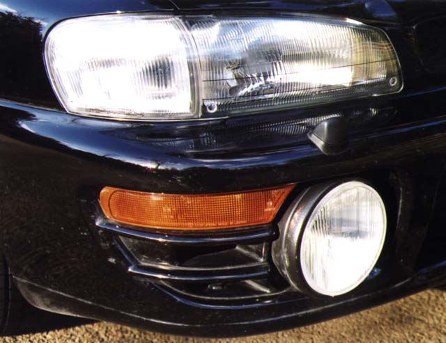
Close up of the Cibie Oscar Plus. Note also the plastic main headlamp protectors, which at just over £30 a pair are certainly cheaper to replace than a headlight if a stone should hit them. The Cibies can also be protected by an additional plastic cover also available from Scoobysport.
Fitting is relatively straightforward with the wiring Scotchlocked onto the existing loom, enabling the lights to come on in parallel to the main beam. Note this is the only legal way to have the light come on and if you wire them directly to the old fog light switch without high-low beam control you will be breaking the law! The brackets fit to the existing holes but it is difficult getting to the bolts to do them up once everything is in place. I would recommend that an extension T-piece socket set is used with a small 1/4in drive socket to get at the fixing bolts. The only real tricky part of the operation is beam alignment which usually requires a bit of packing out of the bolts using a washer or three between the bracket and mounting hole.
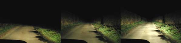
Turn them on and DAYLIGHT!
Dipped, main beam, main beam plus driving lights (note this comparison picture was compiled using my P1 driving lights which are only 65W bulbs as standard).
Vibrating Mirror
Many thanks to Ian Gray for this solution.
1) Remove the plastic cover which sits ,over the roof to mirror
mounting screws , Small screw drive required for this to gently "flip"
it off.
2) Remove all three of the mounting screws to release the mirror
arm from the roof.
3) Remove the central screw holding the plastic spacer onto the
mirror arm mount .
4) Super glue the spacer back onto the arm and quickly refit the
central screw , nice and tight but not enough to crack it .
5) Refit the mirror back onto the roof mount with the three
screws , again quite tight.
6) Leave this fully to dry , 24HRs is best .
7) Now fully test will a fast motorway drive and you will find
the vibration has disappeared and all police cars now become clear.!!!
Not one but two solutions (my we are spoilt ;-). Thanks to Roger Collier for this one...
As an experiment I took a small plastic rod, 3.5 cm long and wedged it between
the glass and the hole in the top of the mirror support, with a lump of blu-tack
at each end. Result - no more vibrations.
An elegant and permanent solution would be a stick with a sucker, such as a
child's toy dart or arrow cut to size.
Roger the bodger.
Do it yourself Quick-Shift
Cheap alternative, that works.
Remove the gearknob/gater. Take one hacksaw, and cut off the top of the gear
stick, leaving about 5mm of thread. If you can, run a 12mm die down the G/S
to extend the threads. Note that you will only make a shallow cut, as the
G/S is 11mm dia, with a 12mm thread "rolled" in. Don't worry if you can't
extend the thread.
Use some electrical/ptfe tape to pack out the stick just bellow the treads
(stops any gearknob movement) and re-fit gater/knob.
Worked for me, Bob R, + a few :-).
Mark.
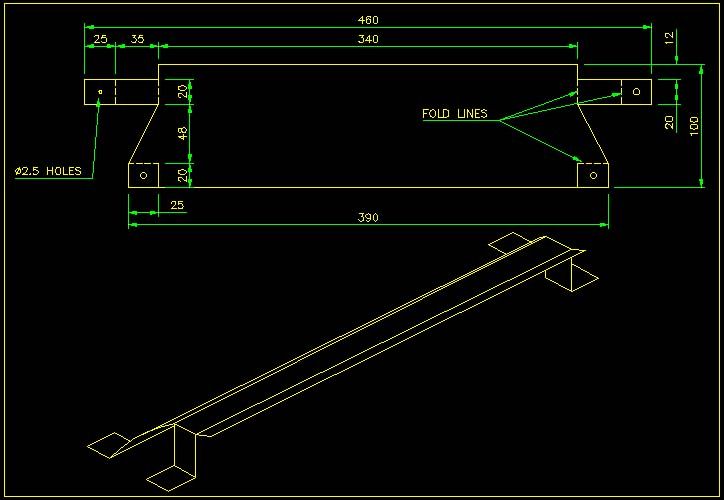
Intercooler Duct - by Tim Whiteside
I made mine from 1.5mm thick aluminium sheet as it was nice and easy
to cut and shape.
Before making it in Aluminium, I would suggest trying it out in card, as
I'm sure that some playing about with the actual dimensions will be needed
first.
Apologies for the isometric drawing which is meant to depict the
'as built' shape of the diverter (scoop) !
Some people who got copies of the drawing last night have already been
asking questions, so here are some extra points:-
Q: You've given dimensions for the holes at the top of your drawing as
2.5mm diam. What diam. are the holes on the bottom of the drawing?
A: The same, the holes don't need to be exact, just to suit your fixing
method (pop rivets or self tappers).
Q; Are the angles for the fold lines critical or is it simply a matter of
trial and error ?
A: The whole thing is trial and error really, the template should ideally
help to cut down on the number of times you have to repeat the process!
What ever you do please carryout a trial run in card first!
Q: Do these holes pick up on existing bolts/screw on the intercooler/ or do
new ones need to be drilled ?
A: New holes will need to be drilled in the bonnet scoop undertray.
Q: Have you verified your design by rolling road or inlet temperature
measurement.
A: The car went on the rollers at PE, at the last gathering (check out Paul
Strong's site) but the duct and my water spray (Allegro parts!) made no
noticeable difference. However Rolling Roads are notorious for not
'appreciating' this type of mod on Scoobs, because the fan blows very
little air over the bonnet into the intercooler.
I haven't taken any temperature measurements, but it would be interesting
to find out what (if any) effect the mods have had to the intake temperature.
Just got to work out how to do it!
Just a thought, the duct was designed (!) around a 98 model Impreza, so if
going on a Pre 97 modes with the offset intercooler, I've no idea whether
it will suit the earlier type!
Hope this helps!
Regards,
Tim
S10OBY
Intercooler Splitter - by Tony Stott/Peter McAlpine
We fitted a splitter in the bonnet scoop, which (obviously) splits the intake air to
ensure that the front half of the intercooler gets an equal share of the
work (he had rightly suspected that most of the airflow hits the rear half,
which then has to work twice as much, leaving the front underused). Bingo!
This resulted in a further 3 degree C drop in temperature difference from input to output intercooler temperature.
Intercooler and Radiator Protection Grill - by Ian Gray
The mess I used for both jobs was galvanized, sprayed mat black with holes approx. I think..( 6mm x 6mm ) as used for making Rabbit/Pet cages available at garden centers etc .
Not too big as it wont stop anything..not too small as the air will be restricted .
To install the grill in the front rads:-
Rough guide ....
1) Remove front grill . the one with the logo on it ...
2) Remove inner headlight mounting screw. This is used to hold the mess in place - left and right
3) Remove / loosen the bonnet latch mounting ( you will need to hold this out of the way while the mesh is installed - a child is ideal for this )
4) Cut mess to size so it fits between h/light mounting screws and covers all rads top to bottom.
5)Slid mesh down in front of rads
6) refit bonnet latch
7) Refit light screws holding mess in place between body/light
8) At the bottom of the mesh I used two tie wraps ( to front grill ) to hold it away from the rad and stop it possibly flapping as if not ,this will move it into the rad and possible cause holes ... Defeats the point of installing it...!!!
The Intercooler grill is in the bonnet ......under the black scoop mounting ..between the bonnet and black scoop plate ....can be seen when the bonnet is up better ..held on by approx. 6 screws ....very easy to make mesh up and refit plate...looks good and works very well .
The first gauge I bought (Badged as Mocal, made by think Automotive),
had a screw on type union on the rear and came with 2m of hard ridged
black plastic pipe with one end already terminated to a union suited
to terminate to the rear of the gauge.
This also came with a crap white nylon t-piece. The black hose would
not fit onto the t-piece due to the black hose being too small.
However the 'suppier' said it would expand when heated !!!
I tried boiling water, a hair dryer, a soldering iron and eventually a
naked gas flame. Only the gas flame had any result and that was to
melt and burn the end.
I Then decided I wasnt going to bodge something on my pride and joy
and took the easy option of visiting a local RS Cosworth Specialist. I
then bought a proper brass t-piece(didnt need this in the end), 2m
of proper flexible rubber turbo hosing (same size and type as the
Imprezas existing waste gate control hose), I also bought another
boost gauge (cant remember the make) from the same chap, with a
fitting at the rear to which the rubber hose pushes straight onto.
I now cut of the union from the end of the hard plastic type hose and
pushed a length of the rubber hose onto this (only overlapping by an
inch) and added a drop of superglue to secure it.
This would then easily connect to the rear of the gauge. (When the
first gauge was connected directly to the rigid hose, the hose
dictated where the gauge would sit as it was so inflexible).
The rigid hose was pushed through an existing grommet just up from the
clutch pedal which comes through into the engine bay hidden behind
three brake pipes (located just above the clutch master cylinder). I
used the rigid hose for this as the proper hose would not probably
fit through this grommet.
Once in the engine bay I again fitted a length of rubber hose onto the
rigid hose, again using a drop of super glue, and connected it to the
manifold on the existing spare manifold port (fitted with a rubber
blanking plug) . This port is found on top of the manifold, just
beneath the ignition coil on the right hand side front (when standing
in front of the engine).
Thats the easy bit done, now the problem of locating the gauge.
I removed the ashtray (I dont smoke and therefore can live without
it), the gauge would just about fit (slightly tight).
I then removed the radio and the console into which the radio,
asktray, cigar lighter & clock( held in with four screws, two hidden
behind the blanking covers which need gently prising off and two
screws covered by the gearstick gaiter.
Once removed, disconnect the wiring plugs for the cigar lighter & clock.
I was then able to take the console out of the car into my workshop
(kitchen floor)
With the gauge held centrally in the slot where the ashtray used to
live, I marked the plastic were it was necssary to cut/file to allow a
snugger fit of the gauge.
It was quite easy to remove enough plastic from the rear of the
console to accomodate the gauge but still allow the ashtray to fit if
I take the boost gauge out at a later date.
I then made a blanking plate from a piece of black plastic (a Sega
mega drive game box [a video box would have done too). This was
carefully cut out with a sharp stanley knife (Ive still got 10
fingers). This plate becomes two once youve cut the two
semi-circular pieces out to allow it to mate up to the side of the
gauge.
The gauge has two threaded studs on its rear. One of these was used
to fasten the gauge to the console using an L-shaped piece of steel (I
used one of those strips of steel with pre-drilled holes, you get with
every car radio you buy).
Once the gauge is bolted in the two blanking pieces were glued in
place from the rear using black silicon sealant. This had the benefit
of filing in any small imperfections, which would allow the green
light from the cigar lighter to shine through.
The gauge was angled slightly to the right prior to gluing.
Once the silicon had cured the gauge light was wired into the cigar
lighter bulb feed.
Fitting is a reversal of removal (as they all say). Take care with the
console as the plastic is very easily scratched. Ensure the rubber
gear lever gaiter is attached to the console before fastening the
screws for the console.
I will admit afterwards, the location is not ideal. Line of sight
would be better. On top of the dash etc. However I couldnt think of a
tidy way of mounting it anywhere else.
If I find a better place, Ill move it and put the ash tray back in !!
I hope this helps,
Regards,
Ian
Intercooler Water Spray - by Tony Stott
Actually, waterspray is a great addition (well in Australia anyway...) I bought an aftermarket windscreen washer kit (plastic 2 litre bottle, clear tubing, motor and wiring), fitted it with a short bracket to the front battery retaining rod (had to reverse the horn to increase clearance, wired it to the standard washer wires and joined the tubing to the washers, then
Added a pressure switch to the firewall, connected to the rh front corner of the inlet manifold, and sent a wire into a coin holder in the centre console to enable me to disable it in wet weather, and then added vacuum tubing to the rubber skirt around the bonnet scoop, where I placed a couple of nozzles from indoor plant trigger spray bottles (these are best for atomising the water. Now, when boost reaches about 8lbs, a little cloud fills the bonnet scoop. Don't laugh! A recent magazine test on a 200bhp turbo car showed a 12 bhp gain! not too shabby for about $A100!
This weekend I am adding a green LED (ie pressure switch has power), and a bright blue LED (water she is pumping!) all inside the same coin holder.
Call me a geek, but its good DIY fun!
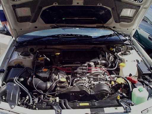
The big one (icspray.jpg) shows the overview. Points to note are:-
- extra small hose leading underneath inner end of right hand ignition leads. This is the pick up point for the pressure switch.
-Pressure switch can go anywhere - here, it is screwed to the firewall at the back right of the intercooler
- the two green water spray bottle nozzles can be seen inside the scoop
- the extra hose is ziptied to the washer hoses (care, the washer hose is very thin, and can be closed if the ziptie is too tight.)
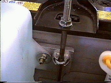
- new washer bottle (with green anti-smear detergent mixture)attaches in front of the battery (see other photo)
Close up of the bracket which attaches the new water bottle to the battery.